Views: 0 Author: Site Editor Publish Time: 2026-06-01 Origin: Site
A turn signal that works only when the stalk is held, wipers that lose an intermittent setting, and high beams that flicker may seem like separate electrical problems. When several of these controls begin failing together, however, the combination switch or its steering-column connections deserve closer attention.
Because bulbs, fuses, relays, motors, wiring, and control modules can produce similar symptoms, replacing the switch immediately can waste time and money. Recognizing how each fault behaves—and whether it changes when the stalk moves—helps narrow the cause and determine when testing or replacement is justified.
Turn-signal trouble often develops gradually. One direction may stop working, or the indicator may operate only while the stalk is held. When small lever movements restore it, worn contacts or loose internal parts inside the combination switch become more plausible.
Mechanical symptoms feel different. A lever that will not stay engaged, has excessive play, or no longer clicks firmly may have a damaged detent or spring. Failure to cancel after the steering wheel returns can involve the canceling mechanism, while a rapid flash rate alone is a reason to check the bulb, socket, or circuit load first.
Unexpected interaction between functions matters too. The signal may cut out over bumps, or touching the stalk may make another lamp flicker. Such behavior connects the fault directly to lever movement.
Wiper failure often affects one mode first. High speed may work while low or intermittent mode disappears, or the delay ring may stop changing the interval. Wipers can also fail to park correctly or ignore the washer command.
A position-sensitive problem makes the combination switch more suspicious. The wipers may run while the lever is held but stop when it is released, or a slight twist may restore a missing speed. Wiper controls commonly provide intermittent, low, high, mist, and washer positions, so testing each setting can reveal one failed contact path.
A total, consistent loss points less specifically to the stalk. The motor, relay, fuse, ground, park circuit, linkage, or power supply may be responsible, while a washer-only fault may come from the pump, hose, nozzle, or connector. The key question is whether the behavior changes when the combination switch moves.
High-beam faults can be confusing because the stalk may include flash-to-pass and latched positions. One mode may work while the other fails, or the headlights may flicker when touched. A worn combination switch can lose continuity in one position while completing another circuit.
Physical feel adds another clue. A stalk that no longer clicks firmly, feels unusually soft, or requires extra pressure may have mechanical and contact wear. Turn-signal movement that changes headlight operation also suggests a shared problem inside the assembly or connector.
One failed headlamp should usually be investigated at the bulb, socket, fuse, ground, or local wiring first. The combination switch becomes more likely when both sides are affected, the failure follows stalk movement, or flash-to-pass and normal high-beam selection behave differently.
Driver-Observed Symptom | Switch Failure Becomes More Likely When | Check First |
Turn signal does not work | It returns when the stalk is moved or held | Bulb, fuse, flasher circuit |
Signal will not cancel | The lever feels loose or lacks a firm detent | Canceling mechanism |
Wipers lose one setting | The setting changes as the stalk moves | Relay, motor, park circuit |
High beams fail | Flash-to-pass and latched modes differ | Bulbs, fuses, headlight relay |
Several controls fail | Signals, wipers, or beams fail together | Shared connector and power supply |
One control affects another | The fault follows stalk movement | Internal contacts or damaged wiring |
A single failed lamp or one missing wiper mode does not confirm a bad combination switch. The diagnosis becomes stronger when several functions from the same steering-column assembly fail within the same period. Turn signals and high beams may both become intermittent, or wipers and washers may respond unreliably while other vehicle systems remain normal. That pattern points toward a shared control point rather than several unrelated failures.
Timing matters too. If the problems began after steering-column trim, steering-wheel, switch, or wiring work, a connector may be loose, misaligned, or damaged. Several unrelated electrical systems failing elsewhere can instead suggest a wider ground, power-supply, harness, or control-module issue. Multiple stalk-controlled failures are therefore a strong clue, not automatic proof.
The most persuasive symptom is often a direct reaction to lever movement. A light may return when the stalk is held between positions, wipers may stop when the control is released, or tapping the housing may briefly restore operation. Clicking, buzzing, grinding, looseness, or an unusually soft action can accompany the fault. One command may even trigger another circuit.
These signs fit worn contact surfaces, weakened springs, broken detents, loose conductive parts, or heat-distorted tracks. A poorly seated connector can create similar behavior, so movement-sensitive symptoms should lead to inspection rather than immediate replacement. Still, when several functions react consistently to the stalk, the combination switch moves near the top of the suspect list.
Start with parts that are easy to reach and likely to fail locally. Inspect bulbs and sockets, compare left- and right-side operation, check the hazard lamps, and verify the fuse with a meter or test light. Normal, rapid, continuous, or absent flasher clicking can further narrow the circuit.
Working hazards can help because hazards and turn signals may share lamps but use different command paths. Normal hazards with failed turn signals make the stalk circuit more suspicious, yet relays, wiring, and control electronics may still be involved. A replacement fuse that blows again indicates an unresolved short or overload.
Separate electrical response from blade movement. Motor noise without blade movement points toward a linkage problem, while blades stopping halfway may indicate a park-circuit or motor fault. Loss of every speed can originate in the motor, relay, fuse, ground, or power feed.
Ice, packed snow, or another obstruction may stop the motor or trigger overload protection, so remove any physical blockage before continuing diagnosis. A washer-only failure calls for checks of the fluid level, pump, hose, nozzle, fuse, and connector. When the symptom never changes as the stalk moves, downstream components deserve more attention than the combination switch.
A damaged connector can imitate nearly every internal switch symptom. Loose terminals may interrupt several circuits, corrosion can create intermittent resistance, and bent or recessed pins may block one command. Melted plastic, darkened terminals, or a burnt smell suggests overheating, so connector inspection can prevent unnecessary combination switch replacement.
Steering-column wiring is vulnerable to vibration, pinching, poor routing, and earlier repairs. A function that returns when the harness moves may come from a broken conductor or loose terminal instead of worn contacts. Control-module faults become more plausible when symptoms extend beyond stalk-operated systems, making vehicle-specific wiring information essential.
Clock-spring faults are often confused with combination switch failure because both components sit around the steering column. A clock-spring problem more commonly affects steering-wheel buttons, the horn, or the airbag warning circuit, especially when the symptom changes as the wheel rotates. A combination switch fault usually reacts to lever movement instead.
Misaligned column covers, broken trim clips, or incorrectly installed parts can also restrict stalk travel. Access procedures vary, and work near an airbag or clock spring requires proper power isolation and vehicle-specific instructions. Keep this alternative in mind without losing focus on the main symptom pattern.
Randomly moving the stalk makes an intermittent fault harder to document. Use the same sequence and note dashboard response, exterior response, lever feel, and whether holding the control changes the result.
1. Test left and right signals in lane-change and latched positions.
2. Check low beams, high beams, and flash-to-pass separately.
3. Operate every wiper speed, intermittent setting, mist function, and washer command.
4. Test any additional controls built into the assembly.
5. Repeat while gently moving the lever within each position.
6. Record whether each fault is constant, intermittent, vibration-sensitive, or position-sensitive.
A structured check makes patterns visible. Examine the wipers, spray jets, turn signals, beam selection, and additional controls separately while noting delayed, incomplete, or inconsistent action. If one setting fails while neighboring settings work, test its individual contact path. If everything fails together, start with shared power, ground, and connector checks.
Look for excessive stalk play, missing detents, cracks, heat discoloration, corrosion, bent pins, recessed terminals, and loose locking tabs. Visible damage can explain an intermittent fault, but a clean exterior does not prove healthy internal contacts. Seat the connector securely before testing the combination switch.
Electrical testing must follow the correct terminal map. Disconnect or isolate circuit power before using resistance or continuity mode, then identify the relevant pins from the vehicle’s wiring diagram. Compare the electrical path in each stalk position and move the lever gently during the reading because a marginal contact may connect at rest but open when shifted. Continuity testing helps determine whether a switch, wire, fuse, or relay provides an unbroken electrical path.
Use this pre-replacement checklist:
● Bulbs, fuses, and obvious downstream faults have been checked.
● Every stalk-controlled function has been tested.
● The connector and steering-column wiring have been inspected.
● The symptom changes with switch position or movement.
● Continuity results support an internal fault.
● The replacement matches the original part number and functions.
Stop when access requires unfamiliar airbag, steering-wheel, or clock-spring work. A shortcut is not worth accidental damage to a safety system.
Replacement is justified when continuity remains inconsistent, the stalk is broken, several shared functions stay unreliable, or terminals show heat damage. Cleaning a connector may remove corrosion, but it cannot restore worn contacts, a fractured detent, or heat-deformed tracks. The decision should follow test evidence.
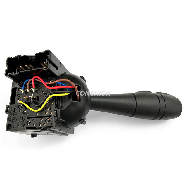
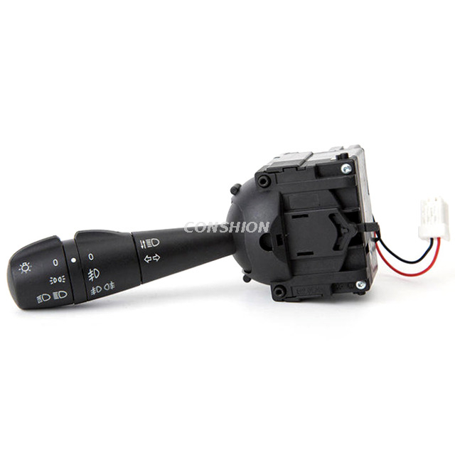
Visual similarity is not enough when ordering a replacement combination switch for a specific vehicle. Confirm the OE reference, connector shape, pin count, vehicle year, trim, steering-column layout, and integrated functions. The Conshion 8201167988 steering-column switch, for example, uses a specified OE reference and 15-pin configuration for defined vehicle applications. A similar-looking unit may use a different pinout or control a different set of functions.
After installation, test signals, beam selection, every wiper mode, washer operation, and added features. A correct combination switch should restore electrical response and mechanical feel. If one function remains faulty, return to the wiring diagram and downstream circuit.
A failing combination switch is most likely when several stalk-controlled functions become unreliable together, when operation changes as the lever moves, or when continuity testing confirms an internal fault. Checking bulbs, fuses, relays, wiring, connectors, and downstream components first helps avoid unnecessary replacement.
Zhejiang Conshion Electrical Group Co., Ltd. supplies combination switch products for turn-signal, wiper, and lighting control applications. Correctly matched components can restore dependable operation, reduce diagnostic uncertainty, and support safer day-to-day driving when the original switch is worn, damaged, or electrically inconsistent.
A: Common signs include intermittent turn signals, missing wiper speeds, failed high beams, loose stalk movement, or several steering-column functions becoming unreliable at the same time.
A: Yes. Because these functions may share one steering-column assembly, worn contacts or an internal fault can disrupt several controls simultaneously or intermittently.
A: Check bulbs and fuses first. A switch fault is more likely when multiple functions fail or operation changes as you move or hold the stalk.
A: Driving may be unsafe if turn signals, headlights, or wipers work unpredictably. These systems support communication and visibility, especially in traffic or poor weather.
A: Test every stalk position, inspect the connector, and use a multimeter with the correct wiring diagram to check whether each selected circuit has continuity.