Views: 0 Author: Site Editor Publish Time: 2026-08-31 Origin: Site
Setting up an aftermarket central locking retrofit requires careful planning. You might be upgrading a classic car. Perhaps you need an exact OEM replacement. Either way, specifying the right parts is crucial. You must choose the correct actuator architecture to match your electrical system. Selecting the wrong actuator creates massive headaches. You might face incompatible wiring harnesses. You could blow critical system fuses. Or worse, your new setup cannot trigger central locking from the driver’s door.
We designed this guide to solve these common electrical design problems. We will deconstruct the distinct electrical circuits found inside 2-wire and 5-wire actuators. You will see how these components behave in the real world. We compare their implementation realities across various vehicle setups. Finally, we provide a clear framework. You will know exactly how to select the right component for your specific door locking project.
2-Wire Actuators act purely as "slave" motors, relying on external modules or switches to reverse polarity and physically move the lock mechanism.
5-Wire Actuators function as "master" units, combining a standard 2-wire motor with an internal 3-wire microswitch that sends lock/unlock signals to the rest of the vehicle.
System architecture dictates the choice: Retrofits requiring a driver-door manual override need a 5-wire unit, while passenger doors or systems fully driven by a keyless entry module only require 2-wire units.
You can safely use a 5-wire actuator as a 2-wire substitute by capping off the three signal wires, but you cannot use a 2-wire to replace a 5-wire without losing central command functionality.
Understanding actuator systems begins by separating components into command and execution roles. Vehicles use distinct electrical signals to manage locking events. Actuators handle these signals differently depending on their internal wiring.
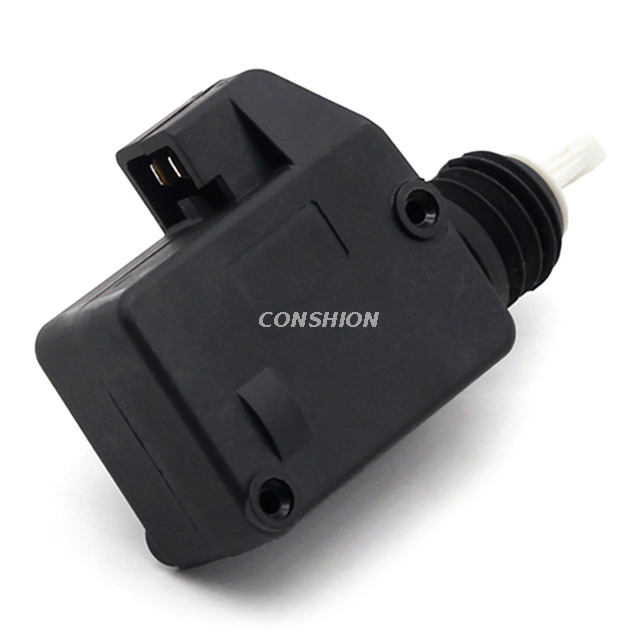
We establish the baseline functionality here. A 2-wire door lock actuator only contains a basic DC motor. It operates strictly as a slave device. It possesses no independent logic. The internal mechanism pushes or pulls based entirely on external voltage. It relies on the polarity of the voltage supplied to its two pins. The motor drives a rack and pinion gear mechanism. This gear physically extends or retracts the connecting rod.
We level up the complexity when discussing 5-wire systems. A 5-wire unit operates as a master controller. It is simply a standard 2-wire motor combined with an internal sensor. This internal sensor is a Single Pole Double Throw (SPDT) microswitch. The switch sits physically linked to the actuator's sliding arm. Moving the arm triggers the switch. It allows the mechanical movement of one door to generate electrical signals.
This internal SPDT switch alters system architecture significantly. It replaces or supplements the standalone physical door lock switch on the door panel. You can turn a physical key in the exterior door cylinder. You can pull the interior lock knob. Either action mechanically moves the master actuator arm. The internal microswitch detects this movement immediately. It then electronically triggers the remaining doors to match.
Two-wire systems represent the simplest form of electrical door locking. They execute mechanical work without providing feedback to the central vehicle computer.
Two-wire systems utilize a resting ground state. Both actuator wires remain grounded when inactive. This prevents accidental triggering. It also protects against short circuits. Actuating the motor requires polarity reversal. A control relay temporarily disconnects one ground. It then sends a positive 12V pulse down that specific wire.
Locking sequence: Wire A receives 12V positive. Wire B remains grounded. The motor turns clockwise.
Unlocking sequence: Wire B receives 12V positive. Wire A remains grounded. The motor turns counter-clockwise.
Resting state: Wires A and B both return to ground.
A 2-wire unit possesses no internal brain. It cannot make decisions. It requires an external command source. You must use an external relay pack or a dedicated keyless entry system. Modern vehicles manage this through a central body control module (BCM). The BCM handles all polarity switching. It also dictates the precise timing of the electrical pulse. A pulse lasting too long will burn out the tiny DC motor.
These units dominate passenger doors and rear doors. Universal aftermarket kits rely heavily on them. Passenger doors only need to receive commands. They rarely need to send commands back to the system. You save space and wiring complexity using a 2-wire slave unit. Installers route two relatively thick gauge wires into the door shell. These wires carry the high current necessary to drive the physical motor.
Five-wire systems bring intelligent communication into the door cavity. They provide mechanical thrust while simultaneously reporting physical status.
Understanding this component requires identifying its specific harness layout. Standard aftermarket kits follow a rigid color-coding system. We break down the five wires into two distinct functional groups.
Green Wire (Motor): Receives power or ground to drive the motor.
Blue Wire (Motor): Paired with green for polarity reversal (identical to the 2-wire setup).
Black Wire (Switching): Serves as the common ground for the internal microswitch.
Brown Wire (Switching): Transmits the "Lock" signal to the external relay.
White Wire (Switching): Transmits the "Unlock" signal to the external relay.
The signal flow begins with a mechanical input. A driver unlocks the door using a physical key. This manual action physically pushes the actuator rod upward. The internal sliding mechanism shifts the SPDT microswitch. The switch connects the Black wire (common ground) to the White wire. The White wire instantly carries a negative ground signal out of the actuator. The motor itself remains unpowered during this manual mechanical event.
This outgoing ground signal travels down the harness. It eventually reaches the central locking relay. In factory setups, it reaches the vehicle's computer module. The module receives this manual unlock request. The module then processes the command. It fires its internal relays. These relays send reversing polarity pulses to the green and blue wires of all other doors. The slave actuators trigger simultaneously. The entire vehicle unlocks synchronously.
Choosing the correct component depends entirely on your system goals. Electrical layouts differ vastly between vintage restoration and modern integration.
Actuator Selection Matrix
System Requirement | Actuator Type Needed | Primary Function |
|---|---|---|
Key turn commands all doors | 5-Wire (Master) | Sends signal to BCM/Relay |
Key fob only (No key use) | 2-Wire (Slave) | Executes commands only |
Passenger/Rear Doors | 2-Wire (Slave) | Executes commands only |
Alarm system override | 5-Wire (Master) | Triggers alarm state change |
Requirement: You want to add central locking where none existed previously. You still want to use your original door keys. You want the passenger doors to lock when you push down the driver's interior knob.
Decision: You must use one 5-wire actuator in the driver’s door. It will act as the master control unit. You install 2-wire actuators in all remaining passenger and rear doors. The master unit detects your manual actions. It triggers the aftermarket relay pack. The relay pack drives the slave doors. Some installers place a master unit in the front passenger door as well. This provides dual-side command capability.
Requirement: You plan to actuate the doors strictly via a key fob. You might use a smartphone app. You do not care if turning the physical key triggers the other doors.
Decision: Two-wire actuators are entirely sufficient for all doors. The central receiver module dictates all logic. When you press the remote, the module fires the relays directly. You do not need physical door switches to initiate commands. You save money and wiring time by skipping the 5-wire master unit.
Requirement: You are replacing a failed factory mechanism inside a modern vehicle.
Decision: You must match the OEM specification perfectly. Did the original door have a key cylinder that controlled all doors? If yes, it requires a 5-wire replacement. Many modern OEM units use even more complex multi-pin connectors. They might include door-ajar sensors or double-locking motors. Always verify the pin count on your original factory harness.
Wiring these systems incorrectly guarantees failure. You must understand the electrical limits of internal components. You must map your circuits before applying power.
Common Mistake: Installers frequently confuse the motor wires with the switch wires on a 5-wire unit. You must treat them as two separate systems. Applying direct 12V power to the brown or white signal wires causes immediate damage. It will instantly destroy the internal microswitch. It can potentially fry the sensitive logic circuits inside your control module. The signal wires are designed solely for low-current ground triggers. Verify your wire colors twice before connecting the battery.
The internal switch inside a 5-wire unit carries a very low amperage rating. It usually handles less than 500 milliamps. You cannot wire the brown and white switch wires directly to the green and blue motor wires of another door. The switch cannot carry the high amperage required to drive motors. They must be wired directly to a relay. Standard 5-pin SPDT automotive relays configured for polarity reversing work best. The microswitch triggers the relay coil. The relay contacts handle the heavy motor current.
Best Practice: Sometimes you only have 5-wire units available. You can safely use a master unit as a slave. This represents a standard industry practice. Shops stock 5-wire units as universal replacements. You simply isolate the three signal wires. You tape off the black, brown, and white wires separately. You leave them disconnected. You connect only the green and blue motor wires. The actuator will function perfectly as a basic 2-wire slave unit. However, you can never upgrade a 2-wire to a 5-wire. A slave unit lacks the physical internal switch entirely.
Mastering automotive lock systems requires understanding component roles. The choice between a 2-wire and a 5-wire unit rarely involves motor quality. It centers entirely on system architecture. You must determine if a door needs to command the system or merely execute commands.
Two-wire units are simple slave motors requiring external relay control.
Five-wire units combine a slave motor with a master control switch.
Classic car retrofits generally require at least one 5-wire unit for physical key integration.
Always verify trigger polarities and relay configurations before routing wires.
We advise all installers to map out their relay configuration first. Verify your vehicle's central locking trigger requirements. Determine whether your module expects a positive or negative trigger. Review actuator specifications closely before starting your project. Order a complete master and slave central locking kit to ensure component compatibility.
A: No. You will lose the ability to lock or unlock all other doors using that specific door's key or manual knob. The system will lose its command sensor.
A: Yes. You can safely ignore and insulate the three signal wires. Connect only the two motor wires. It will function perfectly as a slave unit.
A: Some OEM circuit designs differ slightly. The internal switch might share a chassis ground directly through the metal motor casing. This eliminates the need for a dedicated external ground wire.
A: Yes. They require standard 5-pin SPDT automotive relays. You must configure these relays for polarity reversing. The low-current switch triggers the relay to handle the high motor current.